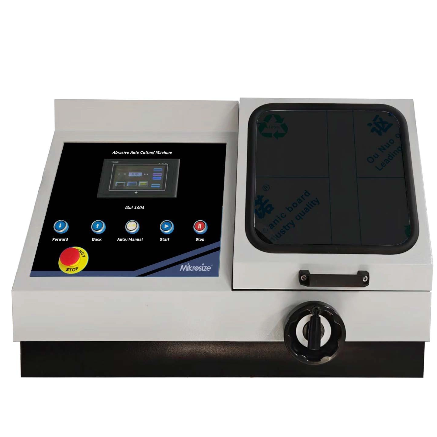
Mikrosize, a trusted global supplier specializing in high-quality Measuring Testing Instruments, has developed the Auto Precision Metallographic Cutter—a cutting-edge solution tailored for precision-driven material processing in metallographic analysis and industrial testing. This advanced cutter operates on the principle of automatic step control, which enables it to precisely regulate both feed speed and feed direction with minimal human intervention, addressing key pain points in cutting scenarios where manual operation falls short. Its core application scope focuses on three critical material types: stress-sensitive materials (such as thin-walled alloys or brittle composites that are prone to microcracks under manual force), difficult-to-cut materials (including high-hardness steels, titanium alloys, and ceramic matrix composites that require consistent force to avoid tool wear), and large-sized materials. The emphasis on large-sized materials stems from the cutter’s structural design: its cutting moving parts—including the spindle assembly, cutting arm, and clamping mechanism—are engineered to handle heavy loads, making manual control not only labor-intensive but also risky for achieving uniform cuts. Automatic control thus becomes not just a convenience, but a necessity for ensuring cutting accuracy and operational safety with large workpieces.
What sets this Auto Precision Metallographic Cutter apart is its superior performance in scenarios where feed speed control is non-negotiable. Unlike manual cutting, which relies on the operator’s experience and is prone to inconsistencies (such as accidental speed fluctuations that damage sensitive samples), automatic control delivers stable, repeatable feed rates—boosting both processing efficiency and sample integrity. Additionally, the cutter integrates mechanical control for feed position adjustment: operators can pre-set coordinates or use precision knobs to fine-tune the cutting path, eliminating the time-consuming trial-and-error of manual adjustment and reducing the risk of position deviations. These advantages make it a preferred choice for users across industries—from aerospace manufacturers cutting large aircraft component samples to research labs processing stress-sensitive metallographic specimens—who prioritize both precision and productivity. When selecting this cutter, three automated-specific indicators demand close attention:
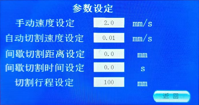
First, cutting speed control: For stress-sensitive materials, the relationship between speed and sample protection is direct—slower, more uniform feed speeds minimize mechanical stress on the material, preventing surface deformation or internal microfractures. Mikrosize’s design allows for stepless speed adjustment within a wide range (typically 0.5–10 mm/min), enabling operators to match the speed to the material’s hardness and thickness. Second, feed direction control: Accurate cutting positions rely on optimizing feed direction: horizontal feed, where the cutting wheel moves parallel to the sample surface, produces a significantly smaller cutting slope (often less than 0.1°) compared to vertical feed, which is critical for samples requiring flat cross-sections for subsequent metallographic polishing and microscopy. For large-sized samples (such as 500mm×300mm metal blocks), the cutter also supports intermittent feed programming—allowing it to pause, adjust position, and resume cutting at different zones, ensuring even heat distribution and avoiding localized overheating that could alter the material’s microstructure. Third, feed load buffering control: A key limitation of fully automatic systems is their inability to quickly sense real-time changes in material resistance (e.g., sudden hard spots in a cast metal sample). To address this, Mikrosize’s cutter is equipped with a dynamic feed load buffering system that uses pressure sensors to detect resistance fluctuations and automatically adjusts feed force within milliseconds. This feature acts as a “safety buffer,” preventing excessive force from damaging large samples or causing premature wear to the cutting wheel—a critical safeguard for high-value workpieces.
Beyond the automated-specific indicators, there are several common performance metrics that apply to both manual and automatic metallographic cutters, and these are equally critical when evaluating Mikrosize’s Auto Precision Metallographic Cutter as part of a comprehensive Measuring Testing Instrument setup. The first metric is cuttable sample size, which directly determines the cutter’s versatility for different applications. This size is governed by the maximum cutting wheel diameter the machine can accommodate (ranging from 150mm to 400mm in Mikrosize’s models) and is further influenced by three key components: the cutting wheel itself (larger wheels cover wider cutting areas), the cutting wheel clamping flange (which secures the wheel and limits overhang), and the clamping platform (the surface that holds the sample, with larger platforms supporting bigger workpieces). For example, a cutter with a 300mm cutting wheel and a 600mm×400mm clamping platform can handle samples up to 350mm in length—ideal for heavy-industry applications like automotive axle component testing.

The second common metric is spindle and flange compatibility. The spindle, which drives the cutting wheel, must be designed to match the wheel’s inner hole size and rotational requirements. Mikrosize’s cutter features a multi-diameter spindle (with adjustable adapters for 20mm, 25mm, and 32mm inner holes) and a precision-machined fastening flange system. The flange’s diameter and thickness are calibrated to distribute clamping force evenly across the cutting wheel, preventing wheel wobble during high-speed rotation (which can cause uneven cuts or wheel breakage). This compatibility ensures that the cutter can work with a wide range of cutting wheel materials—from diamond-impregnated wheels for hard ceramics to resin-bonded wheels for soft metals—without compromising performance.
The third critical common metric is coolant tank performance. Metallographic cutting generates significant heat from friction between the wheel and sample, which can alter the material’s phase structure (e.g., causing thermal oxidation on steel surfaces) or damage the cutting wheel. Mikrosize’s cutter is paired with a high-capacity coolant tank (50–100L, depending on the model) equipped with a dual-stage filtration system and a high-pressure pump. The pump delivers coolant at a flow rate of 15–25 L/min, ensuring constant coverage of the cutting zone, while the filtration system (combining a coarse mesh filter and a fine-particle filter) removes metal shavings and abrasive debris—preventing clogging and maintaining coolant clarity. This setup not only preserves sample quality but also extends the lifespan of the cutting wheel by reducing thermal wear.
When integrating Mikrosize’s Auto Precision Metallographic Cutter into a laboratory or production line—whether as a standalone tool or part of a broader Measuring Testing Instrument ecosystem—additional considerations related to the cutting environment and long-term usability are essential. First, usage and maintenance habits are foundational to preserving the cutter’s precision. Regular cleaning (wiping down the clamping platform and spindle after each use to remove coolant residue), scheduled maintenance (lubricating the feed mechanism every 50 hours of operation, inspecting the sensor wiring for wear), and rust prevention (applying a protective coating to metal components during long periods of inactivity) will significantly extend the machine’s service life and ensure consistent performance over time.
Second, cutting wheel selection must be tailored to the specific sample material and cutting goal. For instance, when cutting aluminum alloys (a soft, non-ferrous material), a resin-bonded silicon carbide wheel with a 120-grit size balances cutting speed and surface smoothness; for high-carbon steel (a hard, ferrous material), a metal-bonded diamond wheel is better suited to resist wear. Mikrosize’s technical team, as part of their Measuring Testing Instrument support services, provides detailed guidelines to help users match wheel type, grit size, and bond material to their application, ensuring optimal results.
Finally, power requirements must be aligned with the cutter’s specifications. High-power models (typically 3–5 kW) of Mikrosize’s Auto Precision Metallographic Cutter—designed for cutting thick, high-hardness materials—require a 380V three-phase power supply to deliver consistent torque to the spindle. This power configuration ensures that the cutter maintains stable rotational speed even under heavy loads, avoiding speed drops that could compromise cut quality. For smaller laboratories or applications with lower power capacity, Mikrosize also offers 220V single-phase models (1.5–2.2 kW) that are suitable for cutting smaller samples or less demanding materials, providing flexibility across different operational environments.
In summary, Mikrosize’s Auto Precision Metallographic Cutter stands out as a core component of modern Measuring Testing Instrument portfolios, combining automatic precision, versatility, and durability to meet the evolving needs of metallographic analysis and industrial material testing. Its thoughtful design—from the automatic step control system to the dynamic load buffering and high-performance coolant tank—addresses the unique challenges of cutting sensitive, difficult-to-cut, and large-sized materials, while Mikrosize’s expertise in Measuring Testing Instruments ensures that users receive not just a tool, but a comprehensive solution supported by technical guidance and maintenance support.


